If you are going through and cleaning up your first CT90 rebuild project, one of the things that is not so obvious is how to disassemble the rear shock absorbers.
The process is pretty straight forward and while it is possible to disassemble the shock absorber without any special tools I find it much easier to make a simple tool to compress the spring on the shock absorber.
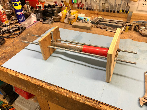
The tool I use to compress the spring in the shock absorber is made using some scrap pieces of plywood and two sections of threaded rod that I had lying around my shop.
The only real important feature is the hole in each piece of plywood that the rod end of the shock absorber will fit through. I've found that a 1-3/8 inch diameter hole is just big enough to let the rod end of the shock through, but still small enough to pick up the the shoulder of the plastic guard on the shock and the end of the spring underneath it.
The threaded rod isn't really critical, but needs to be big enough to carry the load generated while compressing the spring. The threaded rod I am using here is 3/8 inch in diameter and the rods are located 1-1/2 inches or so to each side of the 1-3/8 inch in diameter center hole.
To disassemble the shock absorber you would first mount it in the spring compression tool as shown below. The bolt going through the normally lower mounting hole of the shock is just acting as a simple pin to prevent the prevents the end of the shock from going through the hole and carries the load into that end of the compression tool.
With the shock absorber mounted in the spring compression tool it is now a simple matter of going back and forth and tightening the nuts on each of the threaded rods which will slowly compress the spring of the shock.
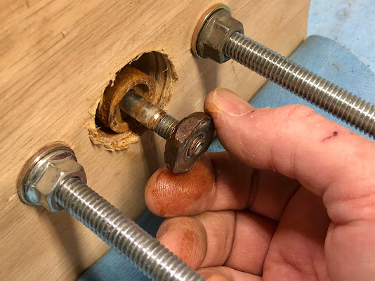
You would continue to compress the spring until you have the rod end exposed like shown in the picture below. It's worth pointing out that while you are compressing the spring the rod end may move along with the spring and not poke out like it is shown in the picture below and its a simple matter of grabbing the rod end and pulling it through the hole.
The rod end in the picture above is actually composed of a thin 20mm hex nut and the rod end itself. Both of these are threaded on to the end of the rod of the shock absorber. To remove the rod end and thin nut you need to hold the thin nut with a wrench and then put a rod of some sort through the hole in the rod end and rotate it counter clockwise while holding the wrench like is shown in the pictures below.
Once the rod end is broken loose then you would continue to unscrew it off of the end of the rod.
Next you would unscrew the thin hex nut from the end of the rod. Depending on how much corrosion there is you might need to grab the rod with a pair of pliers or something else to hold it so the nut can be removed.
With the rod end and thin hex nut removed you would then go and loosen the nuts on the spring compression tool until the spring is fully extended and the shock absorber can be removed from the spring compression tool.
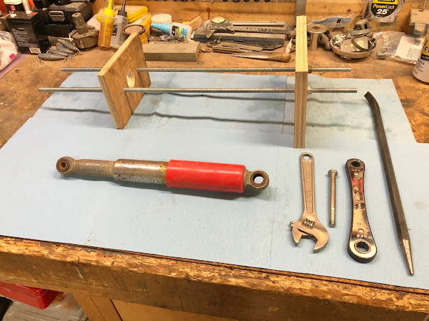
Once you get the shock absorber out of the spring compression tool it comes apart very easily as all the parts just slide apart. The picture below shows all the parts of the shock laid out.
To reassemble the shock after you get it all cleaned up (I haven't done any work on this shock yet, but will use it as an example) you would first slide lower metal spring cover over the shock body until it bottoms.
Next you would slide in the split sleeve that separates the spring from the shock body. The end of the sleeve with the finger goes in first and slide that all the way in until it bottoms.
Next you would slide the rubber bumper over the rod on the shock with the smaller end facing the shock body.
Next you would install the spring with the end with the tighter wound coils going on first and slide the spring on until it bottoms.
With the shock now standing on end with the end of the spring facing up, set the fiber washer on the end of the spring as shown below.
If there wasn't a fiber washer in your shock when you disassembled it, it most likely had designated over time.
If you wanted to make a replacement here are the dimensions of the washer:
Outside diameter: 1.325 inches
Inside Diameter: 0.893 inches
Thickness: 0.045 inches
The fiber washer is made from a very firm/stiff paper gasket like material. I've included this link to an .stl file I have made incase you wanted to experiment with trying a 3D printed washer. I'm going to try and print some using TPU to see how they hold up.
After the fiber washer is setting on the end of the spring you can slide the plastic spring cover over the spring.
If your plastic spring cover was melted or damaged, I've also created an .stl file for the plastic spring cover that is available here at the following link. I have printed these covers using PETG, but I haven't yet used on on the side of the CT90 where it would be next to the exhaust so it will be interesting to see how it holds up or if it melts like the stock ones tend to do over time.
Next while keeping the shock assembly together, reinstall it in the spring compression tool and line up the spring end of the shock so all the components are centered in the hole in the tool.
With everything centered, tighten the nuts on the threaded rods and compress the shock assembly until the rod on the shock protrudes through the hole an adequate amount like as shown in the picture below.
Next reinstall the thin hex nut as shown below with the small turned end facing the shock assembly and then screw it on until it bottoms on the shoulder like in the picture below.
Next install the rod end by screwing it on the rod until it bottoms against the thin hex nut.
Using a wrench to hold the thin hex nut and a bar through the rod end, tighten the rod end against the thin hex nut.
Once you have the rod end tight you can loosen the nuts on the spring compression tool and remove the shock absorber.
Sometimes you'll find that the plastic spring cover seems loose and what you need to do is rotate/move around the spring and plastic cover so that the small turned end of the thin hex nut can pop into place in the center of the plastic cover, fiber washer and end of the spring.
I've also made a video YouTube of the disassembly process here at this link (coming soon!).
I hope you have found this post helpful.
Helpful Links (Shop Manuals, Wire Diagram, Model Information, etc.)


Comments
Post a Comment