Posts

Showing posts from May, 2017

Honda CT90 Engine Reassembly

Image
I have one 1971 CT90 where I was going to rebuild the clutch because the kickstarter just wasn't turning over the engine like it used too,  and I also had a Big Bore kit from DrATV that I wanted to install. My intent was to just do the top end and rebuild the clutch with new disks, but when I opened up the cases to rebuild the clutch pack I found a slick black slime in the bottom of the case.  I didn't like the idea that there could be black slime in the rest of the engine, so I decided to disassemble the entire engine to make sure I cleaned everything out.  Since I was tearing everything apart I thought I would document step by step how everything goes back together in this post in case others were interested in knowing what the inner workings of a CT90 engine look like. Links to Related Posts: My Honda CT90 Clutch and Headset Nut Tool Cut Away of a CT90 Engine - CT90 Engine Exposed! Repairing Damaged CT90 Spark Plug Threads Using a Time-Sert Thread Insert CT90 Clutch P

CT90 and CT200 Axle Information

Image
When I was working on some of my first CT90's and buying parts off of eBay I ended up buying axles that were not correct for the bike because the eBay ad descriptions weren't always clear and I at the time really didn't understand that there were differences in the axles between the various years of CT90's and CT200's. Since I have a bunch of parts setting around from previous project bikes, I thought I would share a few photos and a little info to help someone else trying to pick up the correct axle for their CT90 project.  If I missed something with the info I am providing below, please feel free to comment. From what I have seen CT90 axles can be broken into three groups: CT200's, early CT90's K0 thru K1, and everything K2 and on. Here is a picture of the three groups of axles with the CT200 axles at the top of the photo, the K0 to K1 in the middle, and the K2 and on on the bottom. The rear axle is the top axle in each group and I have also included

Making your own seat foam for a CT90

Image
I have a number of CT90's I am working on right now and they all need new seat foam and covers so I thought I would take a crack at making the foam and sewing all the covers myself. While this post is on making the foam for a CT90 seat, I also have done a post here on how to sew a vinyl seat cover for a CT90 . Here is how I am going about making the foam support for each seat. For the seats I have the covers were in really bad shape and the foam on each seat wasn't much better, but the shot below shows one of the foam supports I removed and a seat pan where I have already removed all the rust and repainted it so it's prep'd and ready to be rebuilt.

How to check a Honda CT90 Ignition Coil

Image
How to Check a CT90 or CT200 Ignition Coil Here is how I perform a basic check of the primary and secondary coils on a 6 volt CT90 ignition coil.  It's also a good idea to check your condenser while you have the coil assembly removed from your CT90 and I outlined how you can check your CT90 condenser at a post here at this link . The coil in the picture below is from a 1969 CT90 I picked up recently.  To check the primary coil I set my meter at the lowest setting to measure ohms and then connect the leads from the meter to the ends of the red and green wires and look at the reading. For this coil the reading is 3.3 ohms which is a little higher then the 2.3 ohms that is used as an upper limit, but should be just fine and is understandable given the coil is 48 years old.

Making a CT90 or CT200 Down Tube Cover

Image
In general, I have a hard time buying anything if I think I can make it myself and with the vinyl down tube covers found on the CT200's and early CT90's, I figured I would take a shot at making my own since they didn't look all that difficult to make. I did have the remnants of a down tube cover off of a CT200 I had owned in the past that was in pretty sad shape, but enough of it was there to get dimensions I could use to make a cover that would be functional and close to the original. This is what the old original cover looked like on the outside and inside:

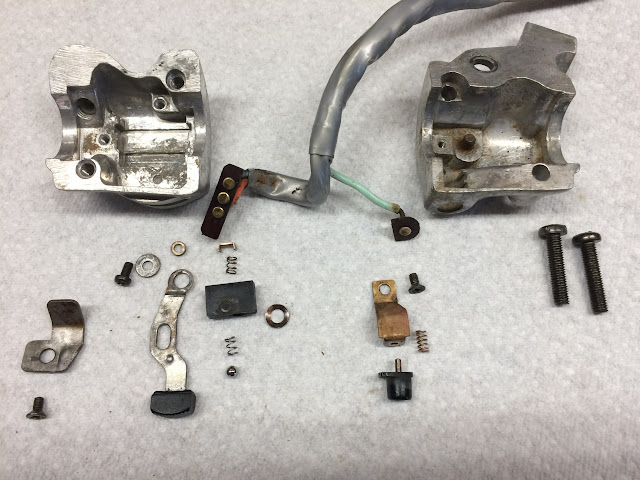
1970 CT90 Turn Signal and Horn Button Brakedown and Assembly

Image
I was going through and cleaning up the left lever lever assembly that retains the turn signal switch and horn button and thought I would share a few shots of the detail parts and how it is assembled. If you are missing or have a rusted detent ball I have found that a 5/32 ball bearing that you can get at a bicycle shop of good hardware store is a good substitute. Here is an overall shot of all the components: