Updated 11/11/17 to correct the section on installing the high range gear where I left out the step to install the splined washer and retaining ring after the high range gear is installed.
I was building an engine for a project CT90 and was reassembling the sub-transmission and thought I would capture the build of that assembly here as a post for future reference and for anyone else to utilize if they happen to be working on this portion of a CT90's engine assembly.
Here is an overall picture of all of the parts that go into the sub-transmission assembly
The first thing that I do when reassembling the sub-transmission is to install the lever that allows you to select the high/low gear range.
The lever has a groove for a small o-ring that needs to be in place and lightly lubricated prior to installation.
Here is a picture of the three parts that will be needed to complete the installation of the lever along with their basic orientation relative to the end of the lever when they are installed.
The lever is installed into the opening on the bottom of the housing and again should be lightly lubricated with grease prior to assembly.
Prior to installing the lever it is worth while to check and make sure the small oil passage to the left of the opening for the lever in the picture below, is clear of debris.
Once the lever is fully inserted the small forked steel plate that will engage the shift fork should be installed as shown below.
And then the circlip should be installed as shown below to complete the installation of the lever.
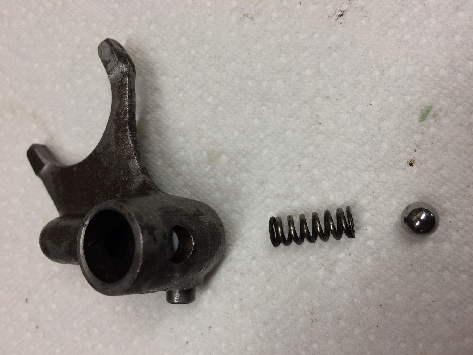
I'll next build up the shift fork assembly. The shift fork also includes a spring and ball bearing that act to hold the shift fork in one of two detents when it is installed on the shift fork shaft.
If you happen to be missing the spring or the ball bearing, the following are dimensions off of the parts I was using in the picture above that might help you hunt down an acceptable substitute.
The Ball Bearing was .250 inches in diameter
Here is the spring information:
Spring Length .610 inches (15.49 mm)
Spring diameter .243 inches (6.16 mm)
Spring wire diameter .045 inches (1.14 mm)
The spring and the ball bearing are assembled into the shift fork through a hole on the side of the fork and I always apply a little grease to these parts prior to installation.
The next step is to install the shift fork shaft into the shift fork. The short end of the shaft should be inserted into the end of the shift fork that has the small nub.
I'll use a punch to depress the ball bearing against the spring to allow the end of the shaft to pass by the ball bearing and then I only push in the shaft until in engages the first detent groove.
The next step is to install the high range gear that has three dog features on the main shaft with the dogs facing up. The high range gear is retained by a splined washer and retaining ring.
The next step is to install the splined washer that rests on top of the high range gear.
And then install the retaining ring in the groove just above the splined washer. You may have to pull out on the splined shaft to get the groove exposed enough to install the retaining ring.
The next step is to install the low range gear and shift fork assembly. While I don't always mention it in each description, I do add lubricant to any of the moving surfaces prior to installation.
Prior to installing these parts I position the range select lever as shown in the picture below and then I would mate the shift fork to the area between the gear and flange with holes on the low range gear, and then lower these parts as a group with the gear over the splined main shaft and the shift fork shaft into its bore in the housing while making sure the nub on the shift fork engages forked plate on the range select level. It sounds like a lot to keep track of, but it really is pretty simple and everything usually just drops into place.
The next step is to assemble the counter shaft and the remaining gear together and then install them into the housing.
It is worth while to make sure the two holes shown on the side of the countershaft in the picture above above along with the bore that runs down most of the length of the shaft, are free and clear of any debris. These holes allow oil to flow to the two journal bearings within the gear, so it is important to make sure these passages are free and clear.
The shaft should be inserted in the end with the smaller gear so that the end of the shaft with the anti rotation pin is as shown in the picture below.
The end of the shaft with the pin will be installed into the bore in the housing with a mating slot for the pin as shown in the picture below.
This gear and shaft assembly should drop easily into the housing, but may require some slight movement of the parts already installed to get it to drop into its final position.
The final step is to install the remaining bearing and cover.
I have always found it easier to instal the bearing into the cover and then install that assembly onto the engine.
Prior to installing the cover assembly, first install the appropriate gasket.
When you are installing the cover it may take a little jiggling of the cover to get all three shafts into their respective bores along with aligning the guide bushing between the cover and engine housing. Take your time and it will eventually drop into place (and sometimes tapping lightly with a small plastic mallet helps).
Once the cover is all the way down, install the four screws and then cycle the range select lever back and forth a few times between the two positions to make sure everything operates smoothly and then you're complete.
One additional thing I learned that I wasn't aware of before, was a difference in the length of screws required to hold the cover on this specific engine.
When I started to build this assembly I didn't have screws for the cover so I took some off another spare engine I had, but when I went to install the screws I found that one screw would not engage the threads in the engine housing. The screws I initially tried to use were off of a K4 engine which had three 6 x 30 mm screws and one 6 x 40 mm screw.
The engine I was building up in this post was from a K6 and what I ended up needing was actually two 6 x 30 mm screws and two 6 x 40 mm screws due to the differences between the K4 and K6 engine housings.
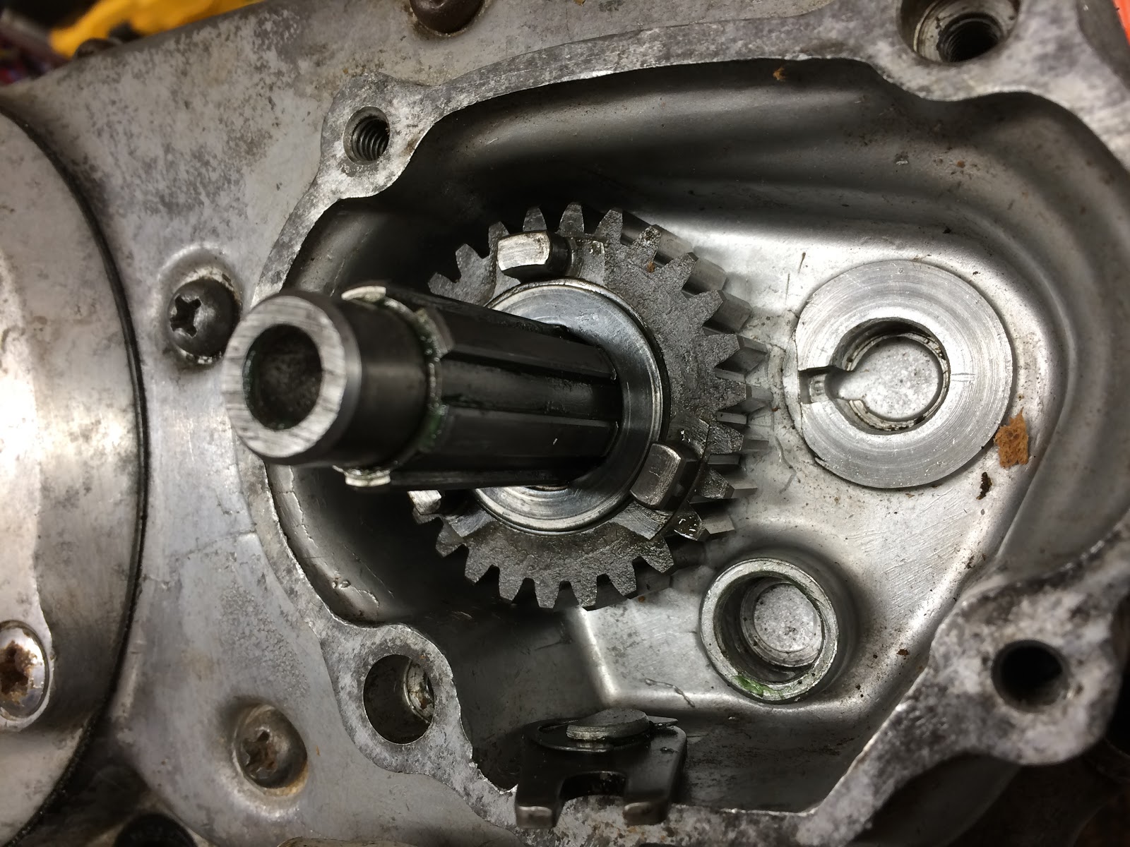
The following is a picture of the K6 engine housing without the cover installed and you can see the upper right and lower left fasteners holes contain a counter bore which drives the need for a longer 6 x 40 mm screw at these locations.
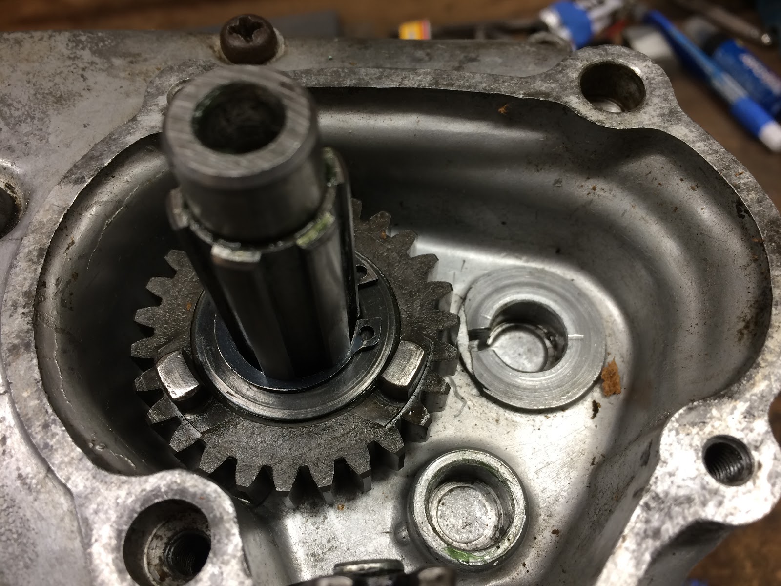
The picture below is of the K4 engine housing without the cover installed and you can see that there is only the single upper right hole that has a counter bore requiring a longer 6 x 40 mm screw.
While the differences are really not all that significant and the fix was simply just finding one more 6 x 40 mm screw, I always find it interesting how many minor differences there are between the different CT90 models.
I hope this post is helpful to other working on or just interested in the CT90 sub-transmission assembly.
Helpful Links (Shop Manuals, Wire Diagram, Model Information, etc.)
Link to page with listing of CT90 parts available on Amazon


Excellent coverage! Thanks, I needed exactly this little lesson on the Hi-Low sub-gearbox! Thank you for posting this!
ReplyDelete